Lab 5 Report
Introduction
In this lab, we used interrupts on the microcontroller to determine the angular velocity and direction of a motor by reading from a quadrature encoder. The motor emits a square wave in the form of two encoder output signals A and B, which are connected to two pins on the MCU respectively. To achieve the highest resolution, on each edge of each encoder pulse, we trigger an interrupt, which goes to that pin/line’s respective interrupt handler where we can perform some calcululations. We also have a timer based interrupt, which allows us to perform time-sensitive calculations such as finding the motor’s speed, and we also use this timer interrupt for a 1Hz display update where we print the angular velocity and direction of the motor to the debug console.
Design and Testing Methodology
In order to approach the design of the project, I first had to look through the reference/programming manual of the STMLK324KC microcontroller, as well as the interrupt lecture slides to understand the flow of logic that needs to be configured to enable interrupts. I used some of the provided header and C files, as well as the timer configuration files from my last lab, however I removed the structs as for this lab we could directly use the stm32l432xx.h header. However, I kept the .c functions the same as it had specially defined functions to configure our clocks and flash. In terms of design for the motor calcualtions, if we trap on any of A’s edges, and B is the opposite signal then we can determine a clockwise direction of motion. Similarly, if we trap on any of B’s edges, and A is the same signal, then we are going clockwise. Otherwise, we are moving in the counter clockwise. So, I connected the input pins (PA9 –> A and PA10 –> B) to interrupt lines (PA9 connects to line 9, PA10 connects to line 10), adn configured the interrupts to trap on both rising and falling edges of the square-wave encoder pulse. Then, on an interrupt, it goes to that line’s IRQ interrupt handler function, where I check for the interrupt on the exact line I care about (9 in EXTI9_5 handler, and 10 in EXTI15_10 handler), clear it by writing 1 to it, and perform my calculations. Here I check for the edges of A and B on the trap to get direction (I can tell which encoder signal I trapped on based on which interrupt handler I went to/which interrupt flag bit went to 1). Then, on these interrupts I also keep a running total of the number of pulses I have in the cw and ccw directions which then gets used in my tim16 interrupt handler function. For tim16, I have the tim 16 timer configured to 1 second, after which it raises the UIF flag and traps into its tim16 interrupt handler. Once I am here, I check how many pulses I had in the second, and divide that by the motors ppr (pulses per revolution), which is 408 from the datasheet to give me angular velocity (rev/sec). I then clear the counter to start fresh for the next 1 second interval. Additionally, once I hit the interrupt handler for the timer, I set a display flag to 1, which if true in the main function, it prints out the direction and angular velocity to the debug console.
The use of interrupts over polling techniques have different pros and cons. With interrupts, we can configure it so that as soon as an event is detected it will trap, pause all other execution, save the architectural state, and handle the interrupt before resuming normal program flow. This requires less hardware, and can almost instantaneously detect an event and handle it. Additionally, priorities can be set so that different interrupts can take precedents over others based on what may be more important. However, sometimes certain interrupts can pause all other execution, and if we want something to happen in parallel it could affect that. On the other hand, polling would require more hardware and continuous checking to determine if an event happened, and there could be a lag in when an event is detected to when it occurs, or it is possible that polling misses the event, in the case that the event happens in between a clock cycle - although unlikely if polling at high speeds.
Calculations: I toggled a pin on my mcu within my main loop, as my polling would be constrained by how fast the main loop can operate, which was 52.8Hz, and then I measured the frequency of the encoder which is 999Hz, and when i performed all the calculations, I found the frequency of how fast my main loop could detect my pulse, and then converted that to rev/s, depending on my 408ppr. 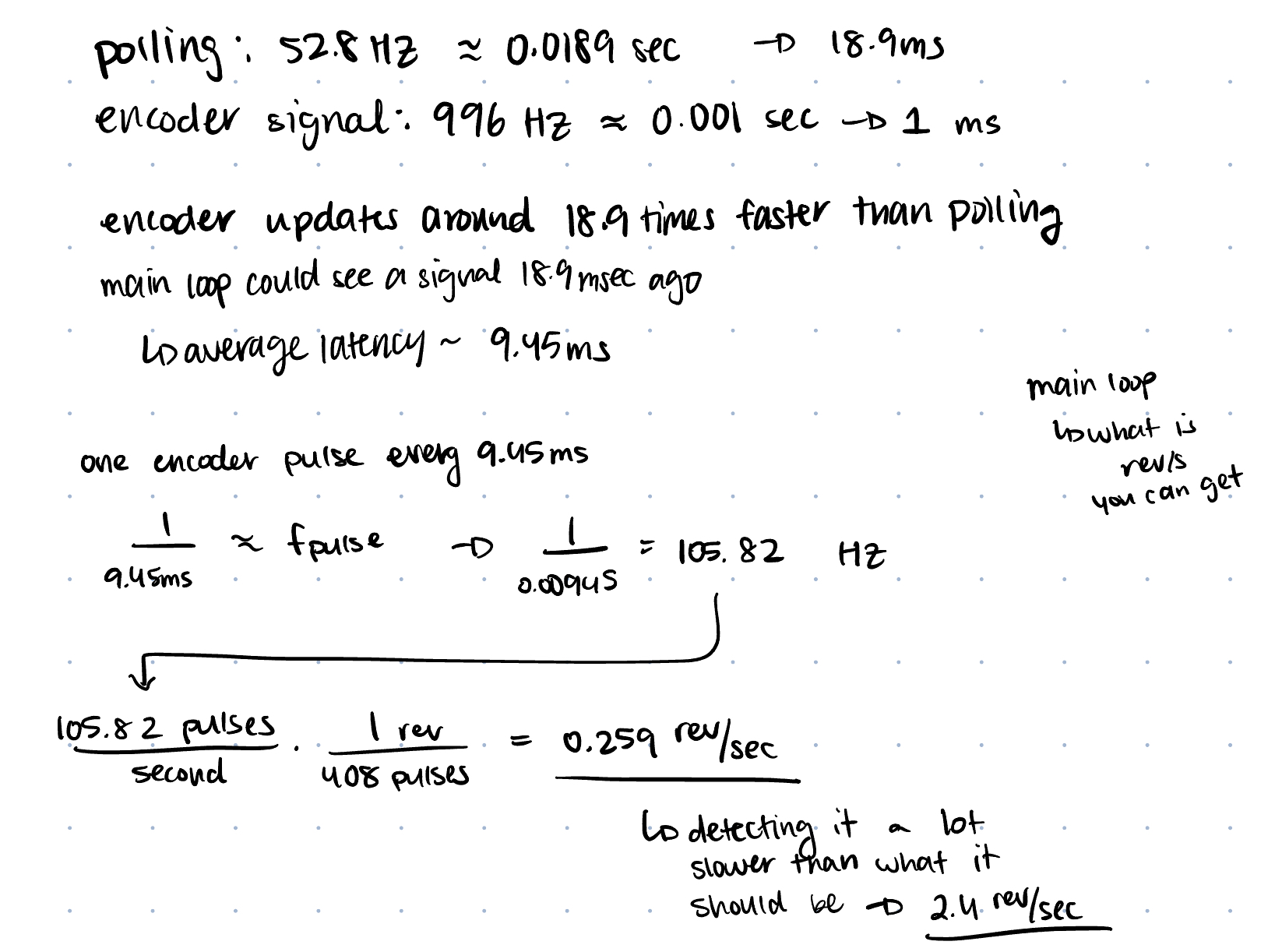 Image 1 above displays the calculations for the polling comparison.
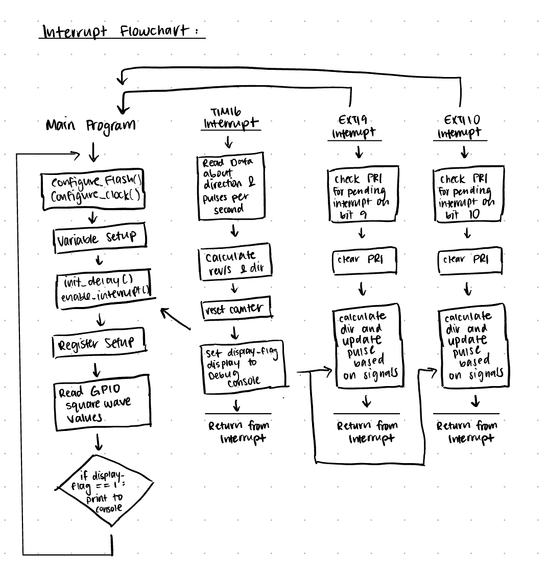 Image 2 above displays the flowchart with the control logic flow, and how interrupts are handeled, and how that is built into the main function.
Technical Documentation:
The source code for the project can be found in the associated Github repository
Schematic
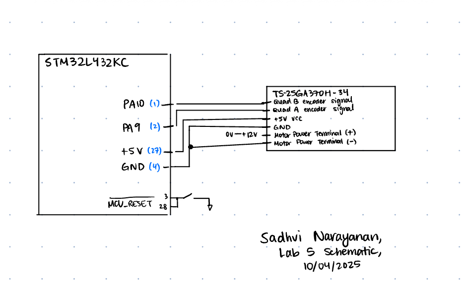
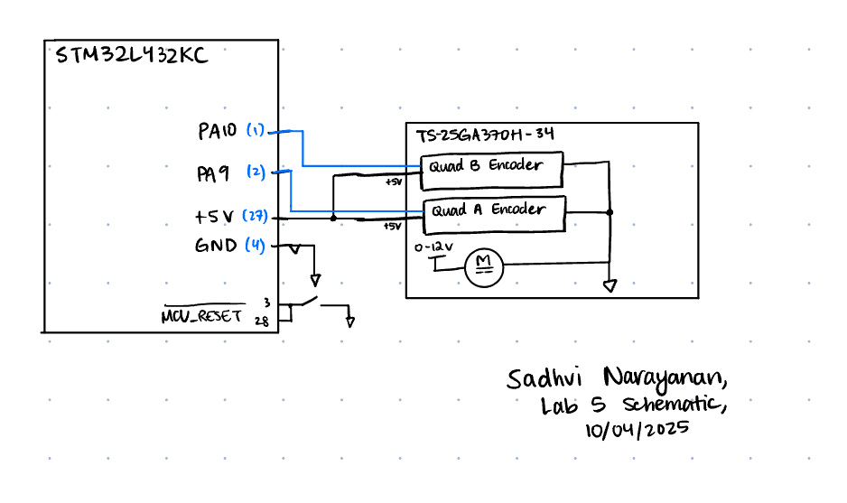 The image above is the schematic of our circuit, which is connected to our motor. Our two encoder input pulses go into pins 9 and 10, and then we connect the motor to a 5V VCC supply from our MCU, and then power the encoders with and external power source. I set up internal pull-ups on pins 9 and 10 within the MCU.
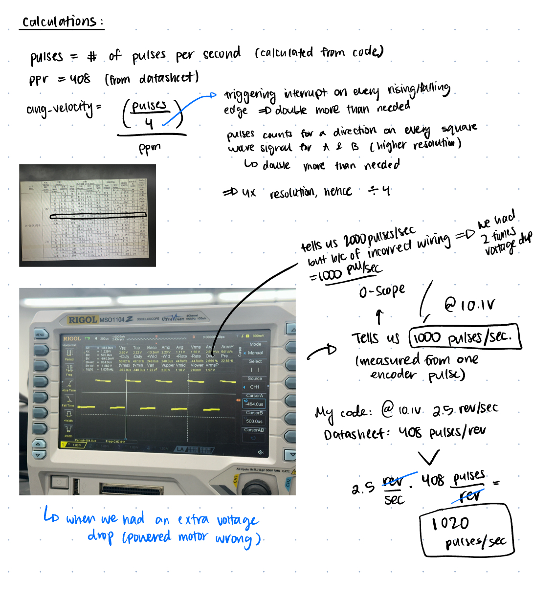 Figure 4 above shows the difference between the actual and expected frequencies, because of the rounding that happens when we set out values to arr.
Results and Discussion
I was able to accomplish all of the prescribed tasks in this project. I also met all the intended design objectives, and was able to check off all the components in the spec, along with the excellence components.
The design performs as expected, and it does seem to display the appropriate angular velocity based on visually how many revolutions occur per second. It also detects the correct direction as well.
Conclusion
The overall design works as expected, and we are able to capture the angular velocity and direction of the motors using a quadrature encoder. I configured interrupts to trap on each edge of the incoming pulses, and based on which trap handler and interrupt bit is high, I would check for the value of the incoming pins to determine the direction, and count the pulses. Additionally, I had a 1 second timer on TIM16 connected to an interrupt, which if it entered the TIM16 interrupt handler, it would calculate the angular velocity using the number of pulses it detected in that second, and the ppr. I spent 12 hours working on this lab.
AI Prototype Summary
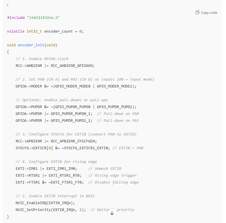
Figure 4 shows the result of the AI prototype, and it is somewhat similar to my code but also very different at the same time. First off, in the code, it uses the masks defined in the header files for the stm32l432xx.h, whereas I directly accessed the bits using bit shifting, and did not use a predefined mask. Additionally, the logic does not consider setting up encoder B’s pin signal on the SYSCFG->EXTICR register which is interesting. I guess, it is not using the highest resolution in the design which is why it is only operating on the rising and falling edge of one of the signals. Furthermore, it is not calculating the direction of the motor based on the values of the encoder pulses, and is also not calculating the angular velocity properly. I also think in the interrupt handler, it is it checking for both bits of the encoder pins at the same time, however in order to determine direction, you need to address the cases differently for the values of the pulses. Furthermore, I am not sure if it knows to use 5V tolerant pins, so this is not really a consideration it made. However, overall it did try to pick pins on the same interrupt line to make it easier to handle with just one interrupt request handler function.